A flip-flop is a circuit that produces an output value of 0 or 1, which remains constant until a pulse (a temporary change to a 1 that returns to 0) from another circuit causes it to shift to the other value. In other words, the output will flip or flop between two values under control of external stimuli. As long as both inputs in the circuit remain 0, the output (whether 0 or 1) will not change. However, temporarily placing a 1 on the upper input will force the output to be 1, whereas temporarily placing a 1 on the lower input will force the output to be 0.
Steps explained:
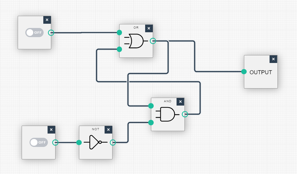
Let us consider this claim in more detail. Without knowing the current output of the circuit, suppose that the upper input is changed to 1 while the lower input remains 0. This will cause the output of the OR gate to be 1, regardless of the other input to this gate. In turn, both inputs to the AND gate will now be 1, since the other input to this gate is already 1 (the output produced by the NOT gate whenever the lower input of the flip-flop is at 0). The output of the AND gate will then become 1, which means that the second input to the OR gate will now be 1. This guarantees that the output of the OR gate will remain 1, even when the upper input to the flip-flop is changed back to 0. In summary, the flip-flop’s output has become 1, and this output value will remain after the upper input returns to 0.
Input A:
Input B: