CPU BASICS
A CPU consists of three parts:
General-purpose registers serve as temporary holding places for data being manipulated by the CPU. These registers hold the inputs to the arithmetic/logic unit’s circuitry and provide storage space for results produced by that unit. To perform an operation on data stored in main memory, the control unit transfers the data from memory into the general-purpose registers, informs the arithmetic/logic unit which registers hold the data, activates the appropriate circuitry within the arithmetic/logic unit, and tells the arithmetic/logic unit which register should receive the result.
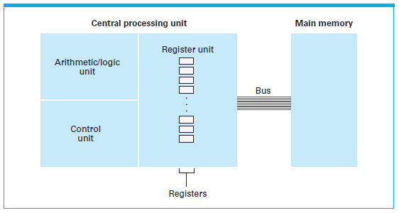
For the purpose of transferring bit patterns, a machine’s CPU and main memory are connected by a collection of wires called a bus. Through this bus, the CPU extracts (reads) data from main memory by supplying the address of the pertinent memory cell along with an electronic signal telling the memory circuitry that it is supposed to retrieve the data in the indicated cell. In a similar manner, the CPU places (writes) data in memory by providing the address of the destination cell and the data to be stored together with the appropriate electronic signal telling main memory that it is supposed to store the data being sent to it.
If the control unit is designed to extract the program from memory, decode the instructions, and execute them, the program that the machine follows can be changed merely by changing the contents of the computer’s memory instead of rewiring the CPU. The idea of storing a computer’s program in its main memory is called the stored-program concept and has become the standard approach used today.
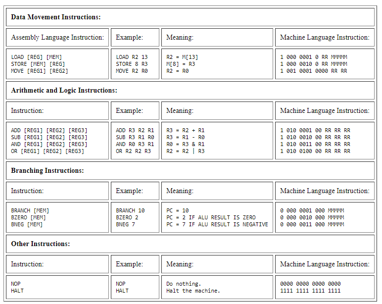
To apply the stored-program concept, CPUs are designed to recognize instructions encoded as bit patterns. This collection of instructions along with the encoding system is called the machine language. An instruction expressed in this language is called a machine-level instruction or, more commonly, a machine instruction.
Based on this design, the task of adding two values stored in main memory then subtracting a value from the result involves more than the mere execution of the addition and subtraction operation. The data must be transferred from main memory to registers within the CPU, the values must be added with the result being placed in a register, this same value is subtracted by another value with the result being placed in a register, and the result must then be stored in a memory cell.
This entire process is summarized by the following animation.
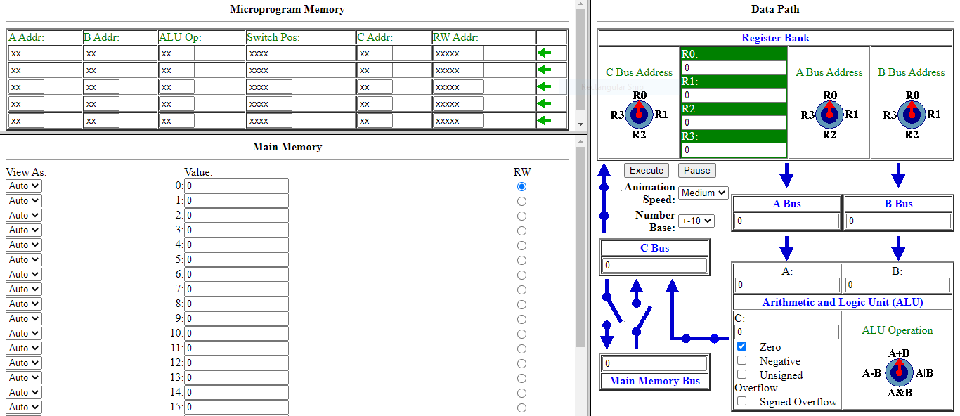 Click buttons a second time to toggle the command's results after being executed.
This simulator is a complete stored program computer. It uses a control unit that translates machine language commands into the microinstructions that carry out the operation. Instructions entered in main memory locations in assembly language are automatically assembled into machine language. In addition, the concept of microprogramming is intuitive in that the bits of each microprogram simply encocde the positions of the knobs and switches.